
- #Use the smith chart to determine the input impedance how to
- #Use the smith chart to determine the input impedance software
- #Use the smith chart to determine the input impedance series
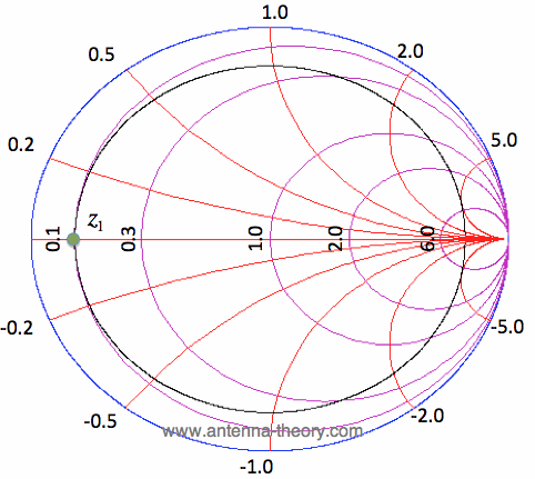
The image below shows an impedance smith chart. They are the most popular, with all references to smith charts usually pointing to them and others being regarded as derivatives.
#Use the smith chart to determine the input impedance series
The Impedance smith charts are usually referred to as the normal smith charts since they relate with impedance and works really well with loads made up of series components, which are usually the main elements in impedance matching and other related RF engineering tasks. While the impedance smith charts are the most popular and the others rarely get a mention, they all have their “superpowers” and can be extremely useful when used interchangeably. Based on this scaling, smith charts can be categorized into three different types

Smith chart is plotted on the complex reflection coefficient plane in two dimensions and is scaled in normalised impedance (the most common), normalised admittance or both, using different colours to distinguish between them and serving as a means to categorize them into different types.
#Use the smith chart to determine the input impedance software
As a result of this, most RF Analysis Software and simple impedance measuring instruments include smith charts in the display options which makes it an important topic for RF Engineers.

Smith chart can be used to display several parameters including impedances, admittances, reflection coefficients, scattering parameters, noise figure circles, constant gain contours and regions for unconditional stability, and mechanical vibrations analysis, all at the same time. However, the Smith charts method of displaying data have managed to retain its preference over the years and it remains the method of choice for displaying how RF parameters behave at one or more frequencies with the alternative being tabulating the information. It was originally developed to be used for solving complex maths problem around transmission lines and matching circuits which has now been replaced by computer software. The Smith Chart, named after its Inventor Phillip Smith, developed in the 1940s, is essentially a polar plot of the complex reflection coefficient for arbitrary impedance.
#Use the smith chart to determine the input impedance how to
We will look into the types of smith chart, its construction and how to make sense of the data it holds. For today’s tutorial, we will be looking at one of the tools that were developed back then and are still currently being used by engineer for RF designs, behold The Smith Chart. In today’s age with different software tools, things are a bit easier but if you go back to the periods before computers became this powerful, you will understand how difficult things were. The third section deals with the Smith chart that is used to simplify the calculation of transmitter line parameters without using equations.Įxercises and probles are also provided to test the readers’s understanding and the answers are given at the end of the chapter.RF Engineering is one of the most interesting and challenging parts of Electrical Engineering due to its high computational complexity of nightmarish tasks like impedance matching of interconnected blocks, associated with the practical implementation of RF solutions. Next is a description on types of measurements performed on microwave systems. The content of the eBook is divided into 3 sections which begin with a description related to the transmission line that carries the signal in the highest frequency in the form of an equivalent circuit consisting of the lump parameters.

So the first compilation of this eBook is related to topic 3, titled Microwave Measuremet. Each topic will be compiled in eBook format separately. The contents of this eBook is written based on the Malaysian polytechnic syllabus for DEP50043 MicroDevices course taken by Electrical and Electronic Engineering (Communication) students.


 0 kommentar(er)
